Motor Test Results, Copper
Compared to Aluminum from CDA
Die Cast Copper Motor Rotors: Motor Test Results, Copper Compared to Aluminum.
- Edwin F. Brush, Jr.1, John G. Cowie2, Dale T. Peters3, and Darryl J. Van Son4
- BBF Associates, 68 Gun Club Lane, Weston, MA 02193 USA
- Vice President, Copper Development Association Inc., 260 Madison Ave., New York, NY 10016 USA
- Senior Advisor, CDA Inc. 27 Raintree Lane, Hilton Head Island, SC 29926 USA
- Van Son Consultants, 4500 Mount Harmony Road, Greenwood, AR 72936 USA
Introduction
Motor manufacturers have long realized that because the electrical conductivity of copper is nearly 60% higher than that of aluminum, substituting copper for alumi-num in the squirrel cage of the induction motor would markedly increase the elec-trical energy efficiency of the machine. Most motors larger than about 200 kW and a few special purpose smaller motors are built with copper squirrel cage struc-tures manufactured by a time consuming and costly fabrication process. The intri-cate squirrel cage of smaller motors is produced by pressure die casting aluminum. Alternative cost-effective manufacturing methods have not been devised. A major barrier to adoption of copper for the rotor has been the high cost resulting from the short die life of the ordinary die steels experienced in die casting copper with its high melting temperature (1083ºC compared to 660ºC for aluminum).
The incentive to solve the problem of short die life and resulting high manufac-turing costs is the 15 to 20% reduction in overall motor energy losses that motor manufacturer models have shown to be possible if copper were utilized in the ro-tor achieving significant energy savings. The U.S. Department of Energy has re-ported that motors larger than 1/6 Hp (1/8 kW) use about 60% of all electricity generated in the United States and that medium power motors (1 to 125 Hp, 0.75 to100 kW) use about 60% of electricity supplied to all motors. In another pa-per at this conference, we have presented the results of a major effort to identify suitable high-temperature die materials and to adapt them to cost effective copper die casting. This work showed that use of nickel-base alloy dies operated at 625 to 650ºC is the path to much extended die life.
This paper summarizes the results of copper rotor die casting trials for four mo-tor manufacturers and the results of manufacturer’s tests of performance of motors equipped with copper rotors compared to the counterpart aluminum rotors. Avail-able data from the literature on motors with copper rotors is also summarized with the new data. A more complete account of details of the rotor die casting and mo-tor performance tests has been presented and published.
Experimental Method
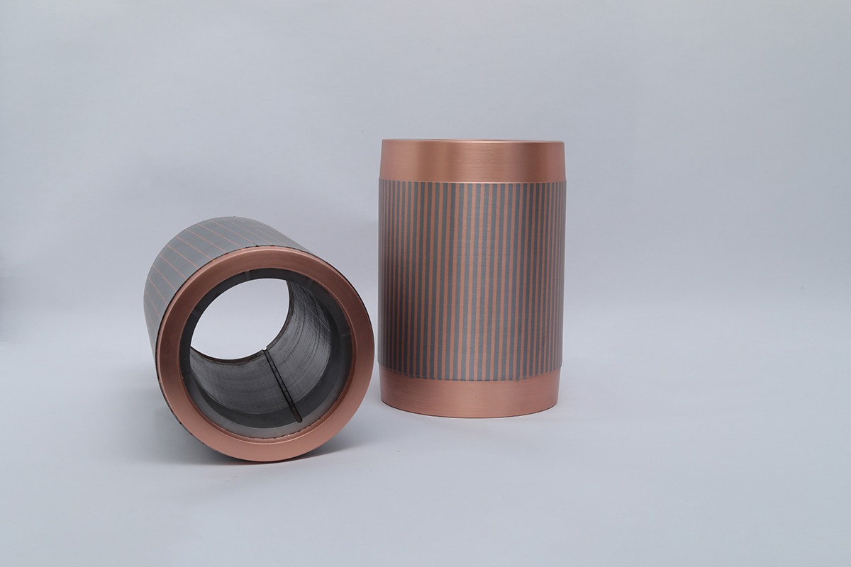
Copper rotors were cast for four motor companies for evaluation in their own fa-cilities. These rotors were pressure die cast in a 660-Tonne real-time shot con-trolled Buhler horizontal machine using H-13 die inserts. Ordinary tool steel dies were used because only a few rotors were required for testing. These die inserts were mounted in a three-platen master mold assembly of the type conventionally used in rotor die casting.
Chopped copper wire rod was inductively melted on a shot-by-shot just-in-time basis to avoid a large holding furnace and the attendant problems of control of oxygen and hydrogen in the molten copper over an extended time. The copper was heated to 1230 °C providing about 150 °C of superheat.
To maintain superheat, a heated shot sleeve surrounded with a thermal wrap was used. The shot sleeves were specifically sized for each rotor size to minimize air entrapment and porosity in the casting.
The real-time shot control capability of the die casting machine provided oppor-tunity to study a number of die casting variables that might affect the quality of the cast copper and the performance of the rotors in motor tests. On the machine used, ram speed can be set at a number of positions and final compacting pressure and duration are adjustable. A wide range of these variables was used to assess the sensitivity of the copper die casting process to machine operating parameters [2].
Because copper is so much hotter than aluminum entering the conductor bar channels, there was some concern that the conductor bar might weld to iron lami-nations or that the properties of the iron would be compromised by heat treatment. Welding of laminations to the copper would increase the magnetic loss component of the total motor losses. On ejection from the machine, half the rotors were water quenched on the theory that rapid cooling would shrink the copper from the iron and would minimize high temperature annealing of the iron. The other half was al-lowed to air cool.
Motor Performance Tests
A total of about 140 rotors were cast for four motor manufacturers to evaluate in their own laboratories. Three companies used dynamometer efficiency tests as per IEEE Specification 112, test method B, as required in the U.S. by the National Electrical Manufacturers Association(NEMA) and the Energy Policy Act of 1992 (EPAct). The fourth company used the IEC 34-2 test method. The IEC method as-sumes a fixed percentage as stray load losses. The IEEE test method is a true watts in vs. watts out efficiency test that segregates the energy losses into five categories of Iron Core Losses, Stator Resistance, Rotor Resistance, Windage and Friction and Stray Load Losses.
The first four are measured directly and the remainder is in the “stray load” category. For reasons explained below, stray load losses are reduced by the copper rotor and it is therefore important to determine this loss rather than assume a value for it.
To ensure an accurate comparison with the corresponding aluminum rotor, a single wound stator was used to test all rotors in each test program.
Participating motor manufacturers were assured confidentiality. Each agreed to disclose test data, but at their request, are not identified.
15 Hp (11.2 kW) Motor
The first copper rotors cast were for a 15 Hp (11.2 kW) motor and were 5.7 inches (144.8 mm) in diameter with a 6-inch stack height containing 14 lbs (6.4 kg) of copper in the conductor bars and end rings. It is important to note that the lamina-tions used here were designed for aluminum; i.e. the slot design had not been op-timized for copper. A number of rotors were cast covering three different injection pressures and one-half were water quenched.
Seven rotors covering these process variables were tested and compared to a large database of similar aluminum rotor motors averaged as a “typical” motor. The same “standard” stator was tested seven times, yielding a spread of stator re-sistance losses ranging from 502 watts to 522 watts. This represents an approxi-mate plus or minus 2% testing error which was assumed to be applicable across all test data. Applying this logic, the data for stator resistance and core iron magnetic loss have been averaged and considered a constant in both copper and aluminum rotors since they are not affected by rotor material.
Test Results
The test results were remarkably consistent across all process variables. The key measure of efficiency yielded virtually no difference with 90.7% as average and variation of only plus or minus 0.1 percentage points. Rotor watts loss aver-aged 157 watts with a maximum variation from 153 to 167 watts. With only seven tests, no pattern could be discerned relative to any of the process variables. The conclusion is that the process is very robust and process variations within the range tested have no predictable effect on final performance results. Although the post-casting cooling method seemed to have no effect on the results, water quenching reduced handling time to one minute versus a 20-minute air-cooling time. This would allow much faster production in a manufacturing plant.
From the remarkable consistency of the test results, we conclude that the cast-ing process is most viable. Results variations were all within test measurement accuracy and no pattern emerged reflecting die casting variables. When compared to historical variation in aluminum rotor motors, these copper rotors were so con-sistent as to deem the data variation insignificant.
Below table shows the IEEE test results as averages for seven rotors tested Rotor re-sistance losses are the key item in rotor material substitution and yielded a 40%reduction in measured losses. This represents 80% of the theoretical maxi-mum value possible in the conductivity difference between rotor materials. This is a very good start for a first attempt at real motors and may be improved further with detail lamination slot design.
- IEEE Loss Segregation test Results for 15 Hp (11.2 kW) Motor
-
Al (W)
Cu (W)
^ W
%
Stator Resistance
507
507
0
0
Iron Core Loss
286
286
0
0
Rotor Resistance
261
157
-104
-40
Windage & Friction
115
72
-43
-37
Stray Load Losses
137
105
-32
-23
Totals
1306
1127
-179
-14
- IEEE Loss Segregation test Results for 15 Hp (11.2 kW) Motor
AI (W) : 507
CU (W) : 507
^ W : 0
% : 0
AI (W) : 286
CU (W) : 286
^ W : 0
% : 0
AI (W) : 261
CU (W) : 157
^ W : -104
% : -40
AI (W) : 115
CU (W) : 72
^ W : -43
% : -37
AI (W) : 137
CU (W) : 105
^ W : -32
% : -23
AI (W) : 1306
CU (W) : 1127
^ W : -179
% : -14
Windage and friction losses are mechanical losses retarding rotation. Al-though these seem to have no relevance to rotor material, they do in this case. The copper rotors cast were had smooth end rings except for projections for balancing weights. They did not include cooling fins on the end rings. With a lower resis-tance rotor, less heat is generated to be dissipated. These rotors, lacking fins, were adjoined on the shaft with an internal circulating fan for stator cooling. These fans are more efficient as they can be sized for their circulating job without having to dissipate rotor heat. As a result, when compared to aluminum rotors with fins, to-tal windage loses were down 37% from 115 watts to 72 watts. Friction in the bearings is assumed to be the same. The cooler running copper rotors allow re-duced windage losses via a more efficient internal fan and reduce the amount of copper required by eliminating the rotor end ring fins.
Stray load losses are the cumulative effect of magnetic transfer efficiency be-tween the stationary stator and the rotating rotor as experienced in the air gap be-tween the two. Consistent air gap and rotor balance also affect stray load losses and there is an electrical component to the magnetic transfer efficiency. Consis-tency in conductivity of rotor conduction bars is critical to proper induction mag-netic transfer. Porosity or nonmetallic inclusions in cast rotor bars can result in variation in effective rotor bar cross sectional area, and therefore resistance, result-ing in variation in the magnetic field in the air gap. This increases stray load losses via inconsistent magnetic flux density between stator and rotor reducing overall efficiency. The seven copper rotors exhibited such rotor bar consistency so as to reduce stray load losses by 23%, from 137 watts to 105 watts. A more ac-curate and consistent casting process might possibly produce similar stay load im-provements in aluminum rotors. It is clear that the die-cast copper rotors contrib-uted to the overall motor efficiency via a consistency not normally achieved in typical motor production.
The substitution of copper as rotor material directly achieved 58% of the total savings and was materially involved in saving the other 24% in windage losses and 18% in casting accuracy stray load losses. The combination resulted in 179 watts of savings or a total of 14% reduction in total losses. These results support the efficacy of both the material and the process. The rotors did not require bal-ancing weights usually used to compensate for rotor bar inconsistencies.
Other Performance Measures
In addition to the loss measurements, the test method itemizes performance issues such as temperature rise above ambient, full load speed and power factor (Table 2). These data reveal a motor having different characteristics than a typical alu-minum rotor motor. Overall efficiency resulted in a solid addition of 1.2 percent-age points added directly to the motor nameplate efficiency. This is significant in that 20 years of motor efficiency improvements have already utilized all of the easy things that reduce losses. Copper rotors represent one of the largest possible reductions in losses without using amorphous steels or superconducting, still ex-otic and very expensive alternatives.
- Performance characteristics of 15 Hp (11.2 kW) motor
-
Al
Cu
Difference
% Change
Efficiency
89.5
90.7
+1.2
+1.4
Temperature Rise, °C
64.0
59.5
-4.5
-7.0
Full Load RPM
1760
1775
+15
+0.85
Slip, %
2.22
1.37
-0.85
-38
Power Factor, %
81.5
79.0
-2.5
-3
- Performance characteristics of 15 Hp (11.2 kW) motor
AI : 89.5
CU : 90.7
Difference : +1.2
% Change : +1.4
AI : 64.0
CU : 59.5
Difference : -4.5
% Change : -7.0
AI : 1760
CU : 1775
Difference : +15
% Change : +0.85
AI : 2.22
CU : 1.37
Difference : -0.85
% Change : -38
AI : 81.5
CU : 79.0
Difference : -2.5
% Change : -3
Temperature rise above ambient is significant in the life expectancy of the motor. The general rule of thumb in the motor industry is that for every 10 degrees Centi-grade hotter a motor runs, life expectancy can be cut in half. With nearly 5°C re-duction in the copper motor temperature rise, we can expect a possible 50% in-crease in motor life when the motor is operated near design capacity. Only real field tests and time would be able to prove this hypothesis, but similar results have appeared in premium efficiency motors. Power factor is down slightly (3%) but is very near measurement accuracy levels. Power factor is only an issue if the elec-tric power utility measures a low power factor for the entire factory facility.
Slip is the difference between the synchronous RPM of the field rotation at 60 Hz (or 50 Hz elsewhere in the world) and the full load RPM of the rotor and shaft assembly. This difference is what creates the torque to rotate the load. The cop-per rotors achieve this torque point with less slip or a higher measured RPM. The implications of a “stiff” motor or one that does not slow down much under load and the higher full load RPM are discussed in Ref. [2]. Starting, breakdown and locked rotor torque values are somewhat reduced in the copper rotor motor and again are discussed in Ref. [2]. Since we have simply substituted copper for alu-minum with no design change to accommodate the copper, these torque factors could be corrected with changes in the cross sectional shape of the rotor bars not necessarily requiring an increase in total copper cross sectional area and cost.
Other Performance Measures
In the larger 25 Hp (18.5 kW) motor, the end rings were 6.5 inches (165 mm) in diameter with a stack height of 9.5 inches (241 mm). The squirrel cage contained 11.4 kg of copper and required melting 17.7kg of copper per shot. The motor manufacturer provided sufficient laminations for 14 rotors. Motor tests of this second set of larger rotors showed even more dramatic results. This in part is due to the use of a rotor lamination slot design specifically designed for copper.
Again there was remarkable consistency in the results for the four rotors tested and compared to the same motor with an aluminum rotor. The rotor losses were 40% lower in the copper rotors and the overall losses were reduced by 23 %. Lower losses led to reduced rotor and stator temperatures. On completion of tests, the temperature of the stator winding of the motor with the copper rotor was 32°C cooler that the aluminum design; the copper rotor was 29°C cooler than the alumi-num rotor. Lower running temperatures mean that smaller internal cooling fans can be used and this had a significant effect in reducing the parasitic component of the friction and windage losses on this motor designed for the copper rotor. Motor temperature translates directly to motor life and maintenance costs. Motors with cast copper rotors, with proper maintenance, would be expected to last longer and be more reliable.
A set of rotors cast for another motor company were for a 4 Hp (3 kW) motor. The end ring was 3.54 inches (90 mm) in diameter, stack height 6.1 inches (155 mm) and contained 3.2 kg of copper. Overall motor losses were reduced by 21% with the copper rotor compared to the conventional aluminum.
Copper rotors for a 5 Hp (3.7 kW) motor were cast for a fourth manufacturer. Rotor I²R losses were reduced by 38% compared to the aluminum counterpart mo-tor, but surprisingly, the iron core loss component was much higher for the motor with the copper rotor. This was apparently due to insufficient consideration of the rotor and stator lamination designs from the aluminum rotor motor used. It ap-pears the iron was almost totally saturated in the aluminum design. The higher current in the copper rotor could not further magnetize the iron and appeared as a large apparent loss.
As shown in Table 3, I²R losses for all motors fitted with copper rotors from this test program showed rotor reductions of about 40% with one smaller motor showing an even greater reduction.
- Rotor I2R losses – copper vs. aluminum
HP
KW
Poles
Al
Cu
Diff.
%
4
3
4
221
92
129
-58
5
3.7
4
-*
-*
-*
-38
15
11
4
262
157
104
-40
25
19
4
410
292
118
-40
*Actual loss values not reported.
Metallurgical examination of cast copper rotors confirmed that there was no in-teraction between the copper conductor bars and iron laminations. Chemical analysis revealed that small amounts of iron (10 to 11 ppm) and oxygen (0.084 to 0.163 wt. %) were picked up during casting. The combined effects of the pres-ence of microstructural defects and chemical contamination reduced the electrical conductivity of the cast copper conductor bars only slightly to 96.8 and 98.7% IACS in the two measurements performed on the first set of rotors cast.
Porosity in the far end ring of the first set of copper rotors appeared to be 2 to 3 percent but did not extend into the conductor bars. The uniformity of conduction paths in these copper rotors shows up as a reduction in stray load losses and had not been expected. No balancing to compensate for uneven weight distribution was required. The larger rotors of the second group cast were more of a problem in this regard showing as much as 25% voids in the first shots and 8 to 10% in the rotors tested for electrical performance. This is apparently due to inadequate venting at the far end ring and excessive oxygen pick-up during the very long melting time (about 13 min.) resulting from the small power supply available. This porosity had little apparent effect on the performance of these copper rotors. Die cast aluminum rotors very often have considerable porosity requiring use of extra aluminum to compensate for porosity and always require balancing.
Copper Rotor Literature Data
Conclusions
Acknowledgements
- Overall Motor Efficiencies And Loss Reductions Via Copper Rotors- Data From This Study And The Literature.
HP
KW
Poles
Eff. Al
Eff. Cu
Difference
Loss Reduction
% Reference
4
3
4
83.2
86.4
3.2
19.0
This study
7.5
5.5
4
74.0
79.4
5.0
19.2
3
10
7.5
4
85.0
86.5
1.5
10.0
4
15
11.2
4
89.5
90.7
1.2
11.4
This study
25
18.8
4
90.5
92.5
1.6
17.6
This study
40
30
4
88.8
90.1
1.3
11.6
5
120
90
2
91.4
92.8
1.4
16.3
5
270
200
4
92.0
90.7
1.0
12.5
5
- Overall Motor Efficiencies And Loss Reductions Via Copper Rotors- Data From This Study And The Literature.
KW : 3
Poles : 4
Eff AI: 83.2
Eff. Cu : 86.4
Diiference : 3.2
Loss Reduction : 19.0
% Reference : This Study
KW : 5.5
Poles : 4
Eff AI: 74.0
Eff. Cu : 79.4
Diiference : 5.0
Loss Reduction : 19.2
% Reference : 3
KW : 7.5
Poles : 4
Eff AI: 85.0
Eff. Cu : 86.5
Diiference : 1.5
Loss Reduction : 10.0
% Reference : 4
KW : 11.2
Poles : 4
Eff AI: 89.5
Eff. Cu : 90.7
Diiference : 1.2
Loss Reduction : 11.4
% Reference : This Study
KW : 18.8
Poles : 4
Eff AI: 90.5
Eff. Cu : 92.5
Diiference : 1.6
Loss Reduction : 17.6
% Reference : This Study
KW : 30
Poles : 4
Eff AI: 88.8
Eff. Cu : 90.1
Diiference : 1.3
Loss Reduction : 11.6
% Reference : 5
KW : 90
Poles : 2
Eff AI: 91.4
Eff. Cu : 92.8
Diiference : 1.4
Loss Reduction : 16.3
% Reference : 5
KW : 200
Poles : 4
Eff AI: 92.0
Eff. Cu : 90.7
Diiference : 1.0
Loss Reduction : 12.5
% Reference : 5
References
- DOE/CS-0147 – U. S. Department of Energy (1980) Classification and evaluation of electric motors and pumps.
- Peters DT, Van Son DJ, Cowie JG, Brush EF Jr.(2002) Improved energy efficiency
- And performance through the die-cast copper rotor. International Conference on Electric Machines, Brugge, Belgium
- Lie S, Di Pietro C (1995) Copper die-cast rotor efficiency improvement and economic consideration. IEEE Trans. Energy Convers. 10 No. 3: 419-424
- Poloujadoff M, Mipo JC, Nurdin M (1995) Some economical comparisons between aluminum and copper squirrel cages. IEEE Trans Energy Convers. 10 No. 3: 415-418
- Private communication with manufacturer.